 |
Serial sequential adder
v.1.0
Example documentation project, author Vladimir Petrović
|
|
Serial sequential adder
v.1.0
Example documentation project, author Vladimir Petrović
|
A top level design of the system. A serial adder with two working modes. More...
Go to the source code of this file.
Entities | |
| fsm_adder | entity |
| Entitiy declaration for fsm_adder component. More... | |
| fsm_adder_behav | architecture |
| Behavioral architechture for serial_adder. More... | |
Serial adder that can work in two modes: 1. input numbers are loaded using the parallel load of two shift registers and output is stored in output shift register, and 2. when input numbers can be any length and are loaded serially and output is read serially.
Modified by: Vladimir Petrovic on 11/15/2016
Modification description: TODO section added.
Reference:
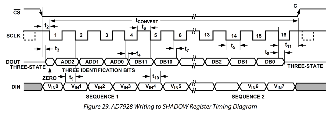
AD7908/AD7918/AD7928 - 8-Channel, 1 MSPS, 8-/10-/12-Bit ADCs with Sequencer in 20-Lead TSSOP datasheet, Rev. D, Analog Devices, 2010.
Definition in file fsm_adder.vhd.
 1.8.12