Serial sequential adder  v.1.0
Example documentation project, author Vladimir Petrović
Generics | Ports | Libraries | Use Clauses
fsm_adder Entity Reference

Entitiy declaration for fsm_adder component. More...

Inheritance diagram for fsm_adder:
shiftreg serial_adder fulladder

Entities

fsm_adder_behav  architecture
 Behavioral architechture for serial_adder. More...
 

Libraries

ieee 

Use Clauses

std_logic_1164 

Generics

reg_width  integer := 4

Ports

reset   in std_logic
 Reset signal.
clk   in std_logic
 clk signal
par_add   in std_logic
 Paralel input/output data write/read control signal.
serial_active   in std_logic
 Serial input/output data write/read control signal.
a_s   in std_logic
 Serial input 1.
b_s   in std_logic
 Serial input 2.
a_p   in std_logic_vector ( reg_width - 1 downto 0 )
 Paralel input 1.
b_p   in std_logic_vector ( reg_width - 1 downto 0 )
 Paralel input 2.
sum_s   out std_logic
 Serial output sum.
sum_p   out std_logic_vector ( reg_width downto 0 )
 Paralel output sum.
out_valid   out std_logic
 Output valid.

Detailed Description

The fsm_adder is a sequential component that can serially add two binary numbers of any length. It has two input shift registers of width defined in generic reg_width and one output shift register of width reg_width+1 since the addition result is one bit longer than the addends. The interface description is shown in Fig. 1.

fsm_adder_block.png
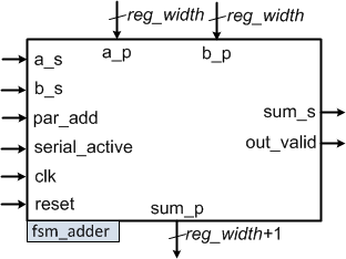
Fig. 1. A block symbol of the fsm_adder component

The component can work in two modes:

  1. Input numbers are loaded using the parallel load of two shift registers and output is stored in output shift register: When the signal par_add is equal to 1, fsm_adder should read the data from parallel input a_p and b_p and store the values to the input shift registers. In that case, addition starts immediatelly and after the output shift register is full, the result can be read from the sum_p parallel output. The fsm_adder generates a logical 1 at the out_valid output whenever the output value is valid.
  2. Input numbers are loaded serially via the a_s and b_s serial inputs, bit by bit at every rising edge of clk when the serial_active signal is equal to 1. After certain delay, output starts to show at the serial output sum_s. When the serial_active signal falls to 0, output can be generated but the data is no longer valid (out_valid is set to 0).

Definition at line 42 of file fsm_adder.vhd.

Member Data Documentation

§ a_p

a_p in std_logic_vector ( reg_width - 1 downto 0 )
Port

Definition at line 65 of file fsm_adder.vhd.

§ a_s

a_s in std_logic
Port

Definition at line 60 of file fsm_adder.vhd.

§ b_p

b_p in std_logic_vector ( reg_width - 1 downto 0 )
Port

Definition at line 67 of file fsm_adder.vhd.

§ b_s

b_s in std_logic
Port

Definition at line 62 of file fsm_adder.vhd.

§ clk

clk in std_logic
Port

Definition at line 52 of file fsm_adder.vhd.

§ ieee

ieee
Library

Definition at line 23 of file fsm_adder.vhd.

§ out_valid

out_valid out std_logic
Port

Definition at line 76 of file fsm_adder.vhd.

§ par_add

par_add in std_logic
Port

Definition at line 55 of file fsm_adder.vhd.

§ reg_width

reg_width integer := 4
Generic

Definition at line 45 of file fsm_adder.vhd.

§ reset

reset in std_logic
Port

Definition at line 50 of file fsm_adder.vhd.

§ serial_active

serial_active in std_logic
Port

Definition at line 57 of file fsm_adder.vhd.

§ std_logic_1164

std_logic_1164
Package

Definition at line 24 of file fsm_adder.vhd.

§ sum_p

sum_p out std_logic_vector ( reg_width downto 0 )
Port

Definition at line 72 of file fsm_adder.vhd.

§ sum_s

sum_s out std_logic
Port

Definition at line 70 of file fsm_adder.vhd.


The documentation for this class was generated from the following file: