 |
Serial sequential adder
v.1.0
Example documentation project, author Vladimir Petrović
|
|
Serial sequential adder
v.1.0
Example documentation project, author Vladimir Petrović
|
Entitiy declaration for serial_adder. More...
Entities | |
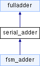
| serial_add_behav | architecture |
| Behavioral and structural architechture for serial_adder. More... | |
Libraries | |
| ieee | |
Use Clauses | |
| std_logic_1164 | |
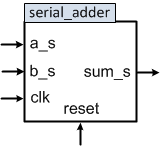
Ports | |
| reset | in std_logic |
| Sequential circuit reset signal. | |
| clk | in std_logic |
| clk signal | |
| a_s | in std_logic |
| Serial input 1. | |
| b_s | in std_logic |
| Serial input 2. | |
| sum_s | out std_logic |
| Serial output sum. | |
Serial adder is a sequential component that adds two N-bit input binary numbers and gives a N+1-bit result. Input and output data are set serially, bit by bit. The result is calculated bit by bit, as the input numbers' bits are set. Input numbers' bits are set at every rising edge of the input clock. The serial_adder stores output carry of one binary addition and uses it as input carry in the calculation of next output bit. serial_adder's interface is shown in Fig. 1.
Definition at line 27 of file serial_adder.vhd.
|
Port |
Definition at line 36 of file serial_adder.vhd.
|
Port |
Definition at line 38 of file serial_adder.vhd.
|
Port |
Definition at line 33 of file serial_adder.vhd.
|
Library |
Definition at line 16 of file serial_adder.vhd.
|
Port |
Definition at line 31 of file serial_adder.vhd.
|
Package |
Definition at line 17 of file serial_adder.vhd.
|
Port |
Definition at line 42 of file serial_adder.vhd.
 1.8.12